Collection of full pictorial information about gadget to review complete

Showing posts with label arduino. Show all posts

Monday, November 22, 2021

Icsp Pins Arduino Nano

Icsp pins arduino nano ~ Using Arduino Project Guidance. An In System Programmer. Indeed lately has been hunted by consumers around us, perhaps one of you personally. Individuals now are accustomed to using the internet in gadgets to view video and image information for inspiration, and according to the title of the article I will discuss about Icsp Pins Arduino Nano We used the Analog and digital pins for communication with different electronic components and sensors.

Arduino Arduinoboardnano Arduino Projects Diy Arduino Arduino Sensors

Arduino Arduinoboardnano Arduino Projects Diy Arduino Arduino Sensors
Source Image @ www.pinterest.com

The Arduino MEGA above is programming an Arduino UNO connecting D51-D11 D50-D12 D52-D13 GND-GND 5V-5V and D10 to RESET. For pin description of Arduino Nano let us assume some basic numbering. Your Icsp pins arduino nano images are ready in this website. Icsp pins arduino nano are a topic that is being hunted for and liked by netizens today. You can Find and Download or bookmark the Icsp pins arduino nano files here. Arduino Arduinoboardnano Arduino Projects Diy Arduino Arduino Sensors

Icsp pins arduino nano | Arduino Arduinoboardnano Arduino Projects Diy Arduino Arduino Sensors

Icsp pins arduino nano ~ You can place your ICSP header basically anywhere on your breadboard or perfboard or PCB simply connect the following lines to the pins you wrote down. Be sure to remember which side everything goes to. With this information let us now see the pin description of Arduino Nano.

So i have to find way to upload sketch to it some way. Not having an AVR programmer I wanted to program an ATMega328P for use as a bare-board Arduino and one convenient way is to use an Arduino board as a an ISP. Touch device users can explore by touch or with swipe gestures.

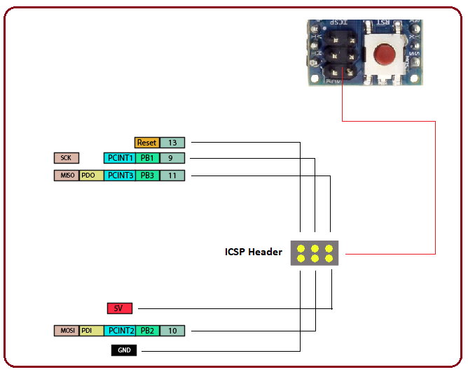
This connector has 6 pins that are arranged as the diagram shows placing the NANO board with ICSP connector facing up leaving the USB port on the right side. MOSI on the ISCP header is connected to MOSI digital pin 11. System April 16 2021 330pm 1.

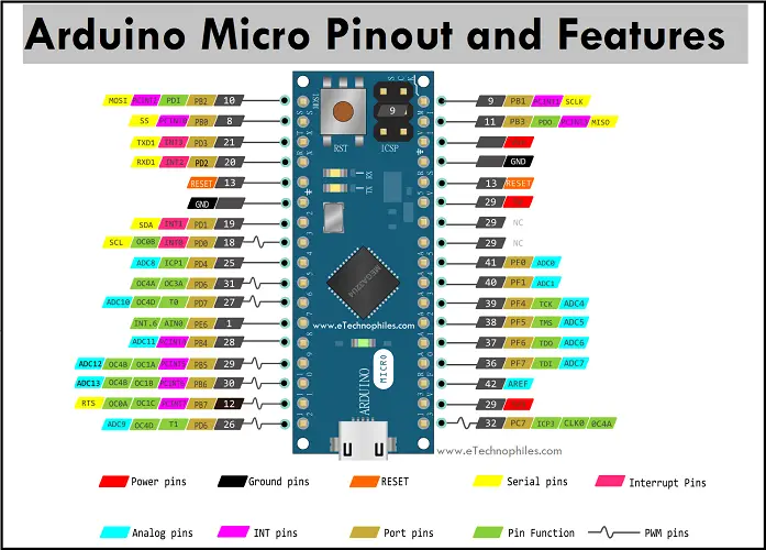
Arduino Nano has a total of 36 pins. How to use a Nano as an Arduino Nano ISP. As you can see in above image my Arduino Nanos USB female pin is broken.

Icsp pins in arduino nano. Nano has a 16 MHz SMD crystal resonator a mini USB. Ive got a project up and running which with bit of help from the forum works beyond brilliant.

Let us now discuss the Vin pins of the Arduino NANO Schematic. So TX is Pin 1 RX is Pin 2 RST is Pin 3 and so on. Please note the connections are made between Arduino UNO IO pins and Arduino NANO ICSP connector.

Then disconnect the Arduino UNO board from the PC. Nando88 July 1 2015 1228pm 1. There are two options to program the controller.

Is it possible to use the icsp pins in the arduino nano to power the arduino with a 5v power source from a circuit I am making. The Arduino Nano is compatible with Windows Max or Linus but Windows are a preferred option. One day i was Google-ing I have read somewhere that a Arduino board can also be programmed.

Two devices are being run by SPI using pins 13 to 11 with 10 and 9 as SS. ICSP stands for In Circuit Serial Programming it is a standard way to program AVR chips. Program Arduino Nano via Uno with ICSP Hello Friends In this tutorial I have shown that how can you program Nano via Uno.

We program an Arduino board through a mini USB cable although. If we look at one side of the board a six-pin header is located for ICSP In-circuit series programming. By using ICSP in-circuit serial programming header.

For example MISO on an Uno or Nanos ICSP header is connected to MISO digital pin 12. Arduino Nano Pinout and Pin diagram. Hello FriendsIn this instructable i have shown that how can you program Nano via UnoAs you can see in above image my Arduino Nanos USB female pin is.

Beside above what is the use of analog pins in Arduino. Program Arduino Nano Via Uno With ICSP. However its one huge mass of cables on the breadboard.

When the auto-complete results are available use the up and down arrows to review and Enter to select. Connect the boards as follows. This Arduino NANO is programmed through its ICSP connector with wires coming from D10-D13 of the programmer UNO board.

Note MISO MOSI and SCK pins taken together make up most of an SPI interface. From the Tools Board Menu select Arduino Nano wAtmega328 and download. On the other side D13 is Pin 16 3V3 is Pin 17 etc.

Arduino Nano has Power pins analog and 14 digital pins. Pinout of Arduino Nano. ICSP and SPI.

The analog pins let you readwrite analog values - basically instead of giving out a voltage of 0 or 5 as with digital they can give a range of voltages between 0 and 5 both as input and output. Each ICSP pin usually is cross-connected to another Arduino pin with the same name or function. Arduino NANO ICSP In-Circuit Serial Programming.

Nov 24 2020 - Atmega 328P based Arduino Nano pinout pin diagram schematic and specifications are explained using images in detail in this post. Out of these 8 are analog input pins and 14 digital inputoutput pins of which 6 can be used as PWM outputs. Arduino Nano ISP.

Let the numbering begin with the TX Pin D1. This list is for 2x3 ICSP headers if you want to use the 2x5 instead see the image. Before concluding the discussion on the Input Output pins it is worth discussing about the ICSP In-Circuit Serial Programming pins that are available on.

Using a Nano as an ISP programmer.

If you are looking for Icsp Pins Arduino Nano you've arrived at the perfect location. We ve got 14 images about icsp pins arduino nano including images, pictures, photos, backgrounds, and much more. In such webpage, we also have number of graphics out there. Such as png, jpg, animated gifs, pic art, logo, black and white, transparent, etc.

Friday, November 12, 2021

Arduino Micro Isp Pinout

Arduino micro isp pinout ~ However there are 2 more pins used by the onboard LEDs which can be quite easily turned into usable pins. The guide also discusses different communication protocols used by the Arduino and a detailed diagram of the Arduino Uno. Indeed lately is being searched by users around us, maybe one of you personally. Individuals now are accustomed to using the internet in gadgets to view video and image information for inspiration, and according to the name of the article I will talk about about Arduino Micro Isp Pinout The Arduino Uno pinout guide includes information you need about the different pins of the Arduino Uno microcontroller and their uses.

Arduino Nano As An Isp Programmer Martyn Currey Arduino Arduino Projects Programmer

Arduino Nano As An Isp Programmer Martyn Currey Arduino Arduino Projects Programmer
Source Image @ www.pinterest.com

At the bottom of this file you need to add the following. You can find the file using this link. Your Arduino micro isp pinout pictures are available. Arduino micro isp pinout are a topic that is being searched for and liked by netizens today. You can Get or bookmark the Arduino micro isp pinout files here. Arduino Nano As An Isp Programmer Martyn Currey Arduino Arduino Projects Programmer

Arduino micro isp pinout | Arduino Nano As An Isp Programmer Martyn Currey Arduino Arduino Projects Programmer

Arduino micro isp pinout ~ It has 20 digital inputoutput pins of which 7 can be used as PWM outputs and 12 as analog inputs a 16 MHz crystal oscillator a micro USB. Arduino Leonardo Introduction. Lets discuss each pin in detail.

This way you can wire up a board with up to 100 keys using the 182 pins in a matrix of 10. Pins are numbered from 1. Arduino Micro pinout.

The pinout of Arduino Micro is shown below. Arduino and ATTINY pinouts. The white Pro Micro.

Apart from this Arduino Micro has a reset button 16MHz crystal oscillator ICSP header and a micro-USB port. To program the bootloader and provide to the microcontroller the compatibility with the Arduino Software IDE you need to use an In-circuit Serial Programmer ISP that is the device that connects to a specific set of pins of the microcontroller to perform the programming of the whole flash memory of the microcontroller. Here is the photo of the setup.

Im collecting them here. Power supply analog and digital pins and ICSP. CIPOCOPI have previously been referred to as MISOMOSI.

Arduino Isp Pinout Um Technologies Pvt Ltd In Depth Tutorial To Interface Micro Sd Card Module With Arduino Arduino Cnc Shield V3 0 Wiring And Pinout Uno Arduino Pinout Using Isp To Burn Bootloader Into Arduino Tutorials Of Cytron Tutoriel Arduino As Isp Youtube Installing An Arduino Bootloader Learn Sparkfun Com. Many Arduino pinouts have been created over the years but they havent been in a stable location. The program is stored in the flash memory of the microcontroller for an Arduino One card this is ATmega328p.

Arduino Micro Specs Capabilities Pinout Arrow Com Using Isp To Burn Bootloader Into Arduino Tutorials Of Cytron Using Arduino Uno As Isp Code And Life Installing An Arduino Bootloader Learn Sparkfun Com Introduction To Arduino Nano The Engineering Projects Interfacing Arduino. Just follow my Pro Micro upgrade guide and solder your wire to the pad of the removed resistors of the RXTX LEDs. Images of wiring and inputoutput pins used with Arduino boards and AtmelMicrochip ATTINY chips.

The Micro can also appear as a mouse or keyboard when connected to the computer. The Arduino Leonardo is a microcontroller board based on the ATmega32u4 datasheet. Arduino isp programmer pinout After developing a sketch with Arduinos IDE we can fill it out and upload it to the Arduino card connected to our PC with a click on the boot button.

Connect the due to the micro Micro to Due. The Arduino Micro is a microcontroller board based on the ATmega32u4 developed in conjunction with Adafruit. The Arduino Micro is based on the ATmega32U4 Microcontroller with the inbuilt USB.

CTS X31 sck. These are actually Pro Micro clones but they seem to work quite well using the Arduino Leonardo profile. Pin 15 to SCK.

Arduino and attiny pinouts. As shown in the Arduino micro pinout above the board has 20 digital IO pins. STOREARDUINOCCMICRO MAXIMUM current per 33V pin is 50mA MAXIMUM current per IO pin is 40mA BOTTOM ATMEGA32U4 PB3 PB1 PB2 CIPO 1 5V 2 SCK 3 COPI 4 RESET 5 GND 6 CIPO SCK COPI PCINT3 PCINT1 PCINT2 USB D-5V USB D USB ID GND Power 5 3 1 6 4 2 ICSP VIN 6-9 V input to the board.

FT232R connected to ISP. It has 20 digital inputoutput pins of which 7 can be used as PWM outputs and 12 as analog inputs a 16 MHz crystal oscillator a micro USB connection an ICSP header and a reset button. Im following this pinout.

See httpwwwgeocitiesjparduino_diecimilabootloaderindex_enhtml Note. DISABLE AUTO-RESET ON THE ISP ARDUINO Skip this step if the ISP Arduino has a 32u4 processor like the Leonardo or Micro. Programmer id arduino-ft232r.

Pin 10 to reset. Out of these 20 pins 7 pins are PWM Pulse Width Modulation pins and 12 pins are analog input pins. The Arduino Pro Micro has 18 easily accessible pins thats theoretically enough for a board with up to 81 keys 99.

Otherwise add a 10uF capacitor to the ISP Arduino with the positive side of the capacitor going to Reset and the negative side of the capacitor going to Ground. The red Pro Micro is set up as ISP using the stock ArduinoISP sketch didnt think anything needed changing. Tools-Port-serial port for ISP Arduino File-Upload.

CONNECT THE ISP ARDUINO TO THE TARGET ARDUINO. It uses Micro USB B cable.

If you are looking for Arduino Micro Isp Pinout you've arrived at the perfect location. We have 14 images about arduino micro isp pinout including images, photos, pictures, backgrounds, and more. In such webpage, we also have number of images available. Such as png, jpg, animated gifs, pic art, symbol, black and white, transparent, etc.

Sunday, October 24, 2021

Arduino Mega Isp Pinout

Arduino mega isp pinout ~ Installing An Arduino Bootloader Learn Sparkfun Com. The input voltage to the Arduino board when it is running from external power. Indeed lately is being searched by users around us, perhaps one of you personally. People now are accustomed to using the net in gadgets to view video and image data for inspiration, and according to the title of this post I will discuss about Arduino Mega Isp Pinout Arduino Mega Pinout.

Arduino Uno Pinout Diagram Arduino Arduino Projects Diagram

Arduino Uno Pinout Diagram Arduino Arduino Projects Diagram
Source Image @ www.pinterest.com

Mega pinout pictures provided on internet show ICSP pin-holes horizontally on the board but vertically on the side picture. Blue is for. Your Arduino mega isp pinout image are ready in this website. Arduino mega isp pinout are a topic that is being hunted for and liked by netizens today. You can Find and Download or bookmark the Arduino mega isp pinout files here. Arduino Uno Pinout Diagram Arduino Arduino Projects Diagram

Arduino mega isp pinout | Arduino Uno Pinout Diagram Arduino Arduino Projects Diagram

Arduino mega isp pinout ~ Kk2 Isp Pinout Mosi To Arduino Pin 11 Miso To Arduino Pin Flickr. Arduino uno and atmega328 pinout. The capacitor has to be placed after the programmer board has been loaded with the ISP sketch.

Arduino mega pinout v2. Goto Tools - Board - Arduino Mega 2560 Now choose the correct Com port via Tools - Serial port - select the port used by youre arduino mega 2560. The Full Arduino Uno Pinout Guide Including Diagram.

How To Use Arduino Mega 2560 As Arduino Isp 3 Steps Instructables. Red are differences where the functionality has moved on Mega2560 compared to UNO. Many Arduino pinouts have been created over the years but they havent been in a stable location.

I can upload via USB but not FTDI. When the sketch is fully uploaded Put a 100nF Capacitor Between 5V and RESET pin on the Arduino Mega 2560 to disable auto reset. It has a crystal oscillator-16 MHz a power jack an ICSP header a USB-B port and a RESET button.

In general this means that the UNO put several functions on one pin and these have moved to separate pins on the Mega. It is designed and developed to provide more number of IO lines both Digital and Analog more flash memory and more RAM when compared to UNO. You can just reprogram it with the bootloader though.

Male Header Pins On Arduino Uno Arduino Stack Exchange. However I am confused about pin numbering of this ICSP block. I believe this is for connecting Arduino as a programmer.

I have gone through the required firmware dates to the USPasp and such. Arduino micro pinout and ISP pins. Now open the latest version of the Arduino IDE currently 0022.

Trying to verify that Arduino Pro Micro ISP is working. So if you use for example an Arduino using ISP to program the chip will overwrite the bootloader and you wont be able to use the Arduino IDE. OC3A Connected to the ATMega and used for USB program and communicating with it.

So which pin is 1 2 and. Whitout this tutorial wont work Step 2. It is available in a 100-pin Quad Flat Package.

Voltage Regulator -The voltage regulator help to. This type of board needs a 10µF electrolytic capacitor connected to RESET and GND with the positive long leg connected to RESET. If you use ISP to program your chip anything on it gets overwritten including bootloaders.

In Circuit System Programming Icsp Using Usbtinyisp And Arduino. BLE Mate 2 bluetooth module to Arduino Uno without FTDI SmartBasic. Arduino Mega ICSP Pinout for ATmega 2560.

However when I attempt to upload to the MEGA boards nothing happens. The Arduino MEGA above is programming an Arduino UNO connecting D51-D11 D50-D12 D52-D13 GND-GND 5V-5V and D10 to RESET. Arduino Mega is based on ATmega2560 Microcontroller an 8-bit AVR Architecture based MCU from ATMEL.

Hello all I am seeking help with programming an arduino MEGA via the ICSP using a USBasp. Annotations are color coded. Time to Burn the Bootloader.

It has reset circuit with capacitor button and resistor to reset the controller. Im collecting them here. It consists of 54 digital inputoutput pins where 16 pins are analog inputs 14 are PWM pins and 6 hardware serial ports UARTs.

Programmer is not responding. Arduino Mega also Uno has a separate block of pin-holes called ICSP. Not USB bus power.

The ArduinoISP sketch will open up and now click upload to upload the sketch to the Arduino Mega 2560. I am even able to upload code to the arduino UNO using this method with no problems via the arduino IDE or microsoft visual studio. Goto File - Examples - ArduinoISP The ArduinoISP sketch will open up and now click upload to upload the sketch to the Arduino Mega 2560.

Inspired by Nicks UNO pinout I did a similar one for the Arduino Mega2560 R3. Arduino Mega 2560 as ISP for ATTINY2313 ATMEGA328P. A push button is used to get 4 cycle low signal on reset pin to.

MEGA ARDUINO THE DEFINITIVE PINOUT DIAGRAM Absolute max 200mA for entire package Absolute max per pin 40mA reccomended 20mA 43 PD0 21 INT0 SCL 43 PD0 21 INT0 SCL. Green have the same function and position as the Arduino UNO R3. After that you are able to use the Arduino IDE again.

Arduino Mega Adk Pinout Arduino Uno R3 From Wavgat Osoyoo Uno Board Fully Compatible With Arduino Uno Rev 3 Attiny And Friends Pinout Diagram Arduino Forum Arduino Turn Your Arduino Into An Isp 5 Steps Instructables.

If you are searching for Arduino Mega Isp Pinout you've come to the perfect place. We ve got 14 images about arduino mega isp pinout adding pictures, pictures, photos, wallpapers, and more. In these page, we also have variety of graphics available. Such as png, jpg, animated gifs, pic art, logo, blackandwhite, translucent, etc.

Thursday, October 21, 2021

Arduino Micro Icsp Header Pinout

Arduino micro icsp header pinout ~ The Arduino Pro Micro doesnt include a reset button 13 pin LED and ICSP header and is smaller in size compared to the Arduino Micro board. - Connect pin 3 of the ICSP header to the SCK pin of your MCU. Indeed recently has been hunted by users around us, perhaps one of you personally. People are now accustomed to using the net in gadgets to view video and image information for inspiration, and according to the title of this article I will talk about about Arduino Micro Icsp Header Pinout ICSP stands for In-Circuit Serial Programming.

40 Keyboards Green Arduino Micro

40 Keyboards Green Arduino Micro
Source Image @ www.40percent.club

So not necessarily to your Vcc pin on your MCU simply put 5V on it. It has 20 digital inputoutput pins of which 7 can be used as PWM outputs and 12 as analog inputs a 16 MHz crystal oscillator a micro USB connection an ICSP header and a reset button. Your Arduino micro icsp header pinout picture are ready. Arduino micro icsp header pinout are a topic that is being searched for and liked by netizens today. You can Get or bookmark the Arduino micro icsp header pinout files here. 40 Keyboards Green Arduino Micro

Arduino micro icsp header pinout | 40 Keyboards Green Arduino Micro

Arduino micro icsp header pinout ~ Skip this step if the ISP Arduino has a 32u4 processor like the Leonardo or Micro. In-Circuit Serial Programming ICSP header is use for SPI communication and to program a microcontroller without disconnecting the microcontroller from the circuit. The ICSP header consists of 6 pins.

It has 20 digital inputoutput pins of which 7 can be used as PWM outputs and 12 as analog inputs a 16 MHz crystal oscillator a micro USB connection a power jack an ICSP header and a reset button. Arduino Leonardo Introduction. The header pins of ICSP are used to program the firmware of the Arduino Micro board.

Note that MISO MOSI and SCK are available in a consistent physical location on the ICSP header. The Micro is a microcontroller board based on the ATmega32U4 developed in conjunction with Adafruit. - Connect pin 1 of the ICSP header to the MISO pin of your MCU.

The Arduino Uno pinout consists of 14 digital pins 6 analog inputs a power jack USB connection and ICSP header. This connector is used also by shields that rely on the SPI interface allowing the. The ICSP header consists of 6.

It is the top view of the ICSP header. Pin 1 is at the bottom left corner of the header as indicated by the white dot on the PCB silkscreen. The Arduino Leonardo is a microcontroller board based on the ATmega32u4 datasheet.

So the header pin numbering is off by 180 degrees. It can also be placed on the breadboard easilyThe board has 7 pwm channels. It is even clarified by written those pins are for ICSP but what does ICSP mean and what are its benefits.

3 5 6 8 10 11 and 13 pins. The structure of the ICSP header is shown below. It is essential for the programming of the Arduino Micro board.

- Connect pin 2 of the ICSP header to your 5V supply on your board. It can be programmed with USB cable or RS232-TTL converter. Has incorrect pin numbering on the ICSP header.

The program or firmware with the advanced functionalities is received by microcontroller with the help of the ICSP In-Circuit Serial Programming header. From 0-53 digital and 0-15 analog can be use as input or output for digital transducer and output devices by pinMode for pin direction digtalWrite to write pin and digitalRead to read pin status. Dec 12 2017 Arduino Micro Pinout.

Digital pins 0-53 Analog 0-15 Total Digital IO pins. Most Arduinos have a little dot near the ICSP header to mark pin 1. The versatility of the pinout provides many different options such as driving motors LEDs reading sensors and more.

CONNECT THE ISP ARDUINO TO THE TARGET ARDUINO. I suggest you buckle up as in this tutorial Ill detail the complete Introduction to Arduino Pro Micro covering pinout pin description features communication and programming and applications. It contains everything needed to support the.

It also contains a reset button a 6-pin ISP reprogramming header and 20 digital IO pins 12 that can be used for analog inputs and seven that can be reconfigured to PWM outputs. Arduino Micro Pinout. The SPI interface - and therefore these pins - is the interface used to program the AVR microcontrollers.

Otherwise add a 10uF capacitor to the ISP Arduino with the positive side of the capacitor going to Reset and the negative side of the capacitor going to Ground. First ICSP In-Circuit Serial Programming is a way that allows us to program the chips when they are in circuits in Arduino it helps in programming Arduino chip. It has 20 digital inputoutput pins of which 7 can be used as PWM outputs and 12 as analog inputs a 16 MHz crystal oscillator a micro USB connection an ICSP header and a reset button.

The new firmware upgrades with the new capabilities are sent in through the microcontroller with the help of this ICSP header. Arduino Micros pwm pins are. In this post well go over the capabilities of the Arduino Uno pinout.

The main feature of the board itself is the USB micro connector which allow it to be easily connected to your computer. Arduino Uno is a microcontroller board based on the ATmega328P It has 14 digital inputoutput pins of which 6 can be used as PWM outputs 6 analog inputs a 16 MHz ceramic resonator CSTCE16M0V53-R0 a USB connection a power jack an ICSP header and a reset button English. See the image below with the ICSP header pinout and do the following.

The placement of these pins is as follows. It also has a 16 MHz oscillator 1 micro USB port 1 ICSP connection header and a RESET button. The Arduino Micro is a microcontroller board based on the ATmega32u4 developed in conjunction with Adafruit.

That is the Arduino Uno V3 Pinout and the ATMega328P pinout as well. Arduino micro pwm pinout. The ICSP pin header is the six pins that are showed in this photo.

If yours doesnt or if it is not very obvious now would be a good time to add a little dot while you have the paint or. 7-9 volt direct input pin used to power up the Arduino board.

If you are looking for Arduino Micro Icsp Header Pinout you've reached the right place. We have 14 graphics about arduino micro icsp header pinout adding pictures, pictures, photos, backgrounds, and more. In these webpage, we additionally provide number of graphics available. Such as png, jpg, animated gifs, pic art, logo, blackandwhite, transparent, etc.

Monday, October 18, 2021

Arduino Nano As Isp Pinout

Arduino nano as isp pinout ~ From the Tools Menu select four options. ICSP stands for In-Circuit Serial Programming. Indeed lately has been hunted by users around us, maybe one of you personally. Individuals now are accustomed to using the net in gadgets to see image and video data for inspiration, and according to the title of this post I will talk about about Arduino Nano As Isp Pinout Each of the 14 digital pins on the Nano can be used as an input or output using pinMode digitalWrite and digitalRead functions.

Arduino Nano As An Isp Programmer Martyn Currey Arduino Arduino Projects Programmer

Arduino Nano As An Isp Programmer Martyn Currey Arduino Arduino Projects Programmer
Source Image @ www.pinterest.com

We go to file - Examples - Arduino as ISP and we open the ArduinoISP example sketch. Each pin can provide or receive a maximum of 40 mA and has an internal pull-up resistor disconnected by. Your Arduino nano as isp pinout photographs are available in this site. Arduino nano as isp pinout are a topic that has been hunted for and liked by netizens now. You can Get or bookmark the Arduino nano as isp pinout files here. Arduino Nano As An Isp Programmer Martyn Currey Arduino Arduino Projects Programmer

Arduino nano as isp pinout | Arduino Nano As An Isp Programmer Martyn Currey Arduino Arduino Projects Programmer

Arduino nano as isp pinout ~ MAXIMUM current per 33V pin is 50mA MAXIMUM current per IO pin is 20mA D13 3V3 AREF 5V RESET GND VIN PB5 ADC0 PC0 ADC1 PC1 ADC2 PC2 ADC3 PC3 ADC4 PC4 ADC5 PC5 ADC6 ADC6 ADC7 ADC7 PC6 D12 D11 D10 D9 D8 D7 D6 D5 D4 D3 D2 GND RESET D0RX D1TX PB4 CIPO PB3 COPI PB2 PB1. Arduino Uno Pinout - ICSP Header. If there is more than one w Arduino as ISP just try each one until it works.

In tools we select Arduino NANO as a board the COM of our USB connected Arduino and we upload the skecth as a normal one like any other to the Arduino NANO. It would be suuuuuuuper convenient if I could simply treat the ICSP pins MISOMOSISCK just as if they were the digital pins 111213 respectively. They operate at 5 volts.

Use attachInterrupt function to configure the Interrupt for rising edge falling edge or level change on the pin. The Full Arduino Uno Pinout Guide Including Diagram Arduino Nano As An Isp Programmer Martyn Currey Pinout Guide Arduino And Attiny Pinouts Introduction To Arduino Nano The Engineering Projects Pololu Usb Avr Programmer V2 User S Guide In Circuit System Programming Icsp Using Usbtinyisp And Arduino. This is the programmer board in use.

Arduino Nano As Isp Attiny85 With Arduino Mega Braunius Engineering Sparkfun Education How To Install An Arduino Bootloader Arduino Nano Pinout Schematics Complete Tutorial With Pin Arduino Arduinoisp Anet A8 Controller S Microprocessor Replacement By Chkmailroot Pinout Guide Arduino And Attiny Pinouts Turn Your Arduino Into An Isp 5 Steps Instructables. Load the example Blink sketch. The ICSP pins are the 3x2 set of pins top center of the board and shown in detail above.

Menu File Examples 11ArduinoISP ArduinoISP. Digital pin 10 from the arduino NANO to pin 29 from the SMD chip CS Praktijk. In Arduino IDE navigate to FilePreferences or press CTLComma and add this URL to Additional boards manager URLs.

Arduino Nano. Uploading sketches to the ATmega328P. Manufacturers like Atmel who work with Arduino have developed their own in-circuit serial programming headers.

Select Sanguino from the Tools Board menu and select the serial port that is your Arduino ISP. It has 14 digital inputoutput pins of which 6 can be used as PWM outputs 6 analog inputs a 16 MHz crystal oscillator a USB connection a power jack an ICSP header and a reset button. Set the Arduino as ISP as the programmer.

So Ive connected these boards this way. Connect the components and wires as shown in the two pictures. STOREARDUINOCCNANO 7-12 V input to the board.

Now click on Tools Burn Bootloader w Arduino as ISP. INTP August 24 2016 137am 1. The name originated from In-System Programming headers ISP.

Image link of wrong pinout killed for the good of mankind. Arduino Nano - Arduino ATMega2560 D11 - ICSP pin4 MOSI D12 - ICSP pin1 MISO D13 - ICSP pin3 SCK 5V - ICSP pin2 5V D10 - ICSP pin5 RST GND - ICSP pin6 GND And after I plug Arduino Nano into USB - windows shows message like USB device unknown. Here the Nano is used as the programmer.

If everything is OK then the programming LED on the Nano ISP should light pin 10 and the LED on pin19 of the ATmega328P should flicker as the boot loader is uploaded. Wiring your ISP connection. This turns the Arduino into an ISP programmer.

Now we open Arduino IDE. To program the bootloader and provide to the microcontroller the compatibility with the Arduino Software IDE you need to use an In-circuit Serial Programmer ISP that is the device that connects to a specific set of pins of the microcontroller to perform the programming of the whole flash memory of the microcontroller bootloader included. Select the Arduino ISP from the example programs in the IDE.

Arduino Uno board is the best choice for the beginners. Digital IO Pins 2 and 3 can be configured as External Interrupts Pins INT0 and INT1 respectively. You can program Arduino nano using ISCP or use the ISCP of Arduino Nano to program other Arduino Boards.

ICSP pinout here. Wiring your ISP connection. The Arduino Uno is a microcontroller board based on the ATmega328.

These pins enable the user to program the Arduino boards firmware.

If you are searching for Arduino Nano As Isp Pinout you've come to the ideal place. We ve got 14 images about arduino nano as isp pinout including images, pictures, photos, wallpapers, and much more. In these webpage, we additionally provide variety of graphics out there. Such as png, jpg, animated gifs, pic art, logo, black and white, translucent, etc.

Wednesday, October 13, 2021

Arduino Leonardo Icsp Header Pinout

Arduino leonardo icsp header pinout ~ Nov 24 2020 - Atmega 328P based Arduino Nano pinout pin diagram schematic and specifications are explained using images in detail in this post. It has an ATmega32U4 microcontroller at its heart. Indeed recently has been searched by consumers around us, maybe one of you personally. People now are accustomed to using the net in gadgets to see image and video data for inspiration, and according to the name of the article I will discuss about Arduino Leonardo Icsp Header Pinout Ive been trying to get 2 Leonardos to talk to each other over SPI I know I should post photos of how theyre connected and what code Im using but this should be something that someone can answer without having to debug my rotten code.

Arduino Leonardo Pinout Schematic And Specifications In Detail

Arduino Leonardo Pinout Schematic And Specifications In Detail
Source Image @ www.etechnophiles.com

On the Arduino UNO in the following image we have highlighted in red the connections on the female strips. Arduino Leonardo Pwm Pinout. Your Arduino leonardo icsp header pinout pictures are available. Arduino leonardo icsp header pinout are a topic that is being searched for and liked by netizens today. You can Get or bookmark the Arduino leonardo icsp header pinout files here. Arduino Leonardo Pinout Schematic And Specifications In Detail

Arduino leonardo icsp header pinout | Arduino Leonardo Pinout Schematic And Specifications In Detail

Arduino leonardo icsp header pinout ~ Be sure to remember which side everything goes to. Atmega32u4 5v 16mhz Expansion Board Module Diy Kit Micro Usb. The Arduino Leonardo is a microcontroller board based on the ATmega32u4 microchip.

Arduino Uno R3 Stackable Shield Header Set W Icsp Tall Stack. Each of the 20 digital io pins on the Arduino Leonardo can be used as an input or output using pinMode digitalWrite and digitalRead functions. Arduino Leonardo Introduction.

The Full Arduino Uno Pinout Guide Including Diagram. Arduino Leonardo Pinout Diagram - Use Arduino for Projects. Input and Output.

And the board features 20 digital inputoutput pins a 16 MHz crystal oscillator a micro-USB port an ICSP header pins and a RESET buttonArduino Micro pinout specifications schematic and datasheet is given below. It consists of a total of 20 digital IO pins of which 7 can be used as PWM outputs and 12 as analog inputs a power jack a micro USB port a 16 MHz crystal oscillator an ICSP header and a. Arduino Board Comparisons Picking The Right Board Pubnub.

You can place your ICSP header basically anywhere on your breadboard or perfboard or PCB simply connect the following lines to the pins you wrote down. Jan 07 2015 Arduino Leonardo Introduction. It has 20 digital input output pins 7 of which can be used as PWM output 12 of which can be used as analog input 16Mhz crystal micro usb socket power socket ICSP connector and reset button.

I have connected the ICSP headers to each other Ive tried it with just 3 jumpers - SCK MISO MOSI with 4 jumpers RESET with 5 jumpers Vcc. Arduino Uno is based on the ATmega328 by Atmel. The Arduino Micro is a miniature version of the Arduino Leonardo board.

Adrotate banner7 This is a 16 megahertz chip on in its. The Arduino Leonardo is a microcontroller board based on the ATmega32u4. That is the Arduino Uno V3 Pinout and the ATMega328P pinout as well.

It is even clarified by written those pins are for ICSP but what does ICSP mean and what are its benefits. The Arduino Leonardo is a microcontroller board based on the ATmega32u4 It has 20 digital inputoutput pins of which 7 can be used as PWM outputs and 12 as analog inputs a 16 MHz crystal oscillator a micro USB connection a power jack an ICSP header and a reset button. Arduino Uno is a microcontroller board based on the ATmega328P It has 14 digital inputoutput pins of which 6 can be used as PWM outputs 6 analog inputs a 16 MHz ceramic resonator CSTCE16M0V53-R0 a USB connection a power jack an ICSP header and a reset button English.

The Arduino Uno pinout consists of 14 digital pins 6 analog inputs a power jack USB connection and ICSP header. A slightly different chip to the uno is actually a very similar form factors of the you know but its actually a little bit different in quite a few ways in particular has a very different chip on board. The Atmega32u4 based Arduino Leonardo Pinout Pin diagram Schematic and Specifications are given in detail in this post.

They operate at 5 volts. Arduino leonardo pinout. This list is for 2x3 ICSP.

The Arduino Leonardo is a microcontroller board based on the ATmega32u4 It has 20 digital inputoutput pins of which 7 can be used as PWM outputs and 12 as analog inputs a 16 MHz crystal oscillator a micro USB connection a power jack an ICSP header and a reset. The Atmega32u4 comes with a built-in bootloader which makes it convenient to flash the Arduino board with our code. The Arduino Leonardo is a microcontroller board based on the ATmega32u4 It has 20 digital inputoutput pins of which 7 can be used as PWM outputs and 12 as analog inputs a 16 MHz crystal oscillator a micro USB connection a power jack an ICSP header and a reset button.

Each pin can provide or receive a maximum of 40 mA and has an internal pull-up resistor disconnected by default of 20-50 kOhms. In yellow the ICSP connector that connects to the ATmega328P. Please note that the Rev3 board has an ATMega 16U2 chip that manages the USB connection and also that chip can be reprogrammed via a dedicated connector labeled ICSP2 just.

In this post well go over the capabilities of the Arduino. The ICSP pin header is the six pins that are showed in this photo. In Arduino Leonardo pwm pinouts are 3 5 6 9 10.

The ICSP 6-pin header. The versatility of the pinout provides many different options such as driving motors LEDs reading sensors and more. First ICSP In-Circuit Serial Programming is a way that allows us to program the chips when they are in circuits in Arduino it.

It has 20 digital inputoutput pins of which 7 can be used as PWM outputs and 12 as analog inputs a 16 MHz crystal oscillator a micro USB connection a power jack an ICSP header and a reset button. More like this. It is an Atmega32u4 based microcontroller board.

If you are searching for Arduino Leonardo Icsp Header Pinout you've come to the ideal place. We have 14 graphics about arduino leonardo icsp header pinout adding pictures, photos, pictures, backgrounds, and more. In these web page, we additionally have number of graphics out there. Such as png, jpg, animated gifs, pic art, symbol, black and white, translucent, etc.

Friday, September 24, 2021

Icsp Pinout Arduino Mega

Icsp pinout arduino mega ~ The Arduino Mega has in total one 33V pin and four 5V pins which are able to provide a current up to 50 mA. Arduino Mega Pinout. Indeed recently is being searched by users around us, maybe one of you personally. Individuals are now accustomed to using the internet in gadgets to view video and image data for inspiration, and according to the name of this article I will talk about about Icsp Pinout Arduino Mega An Arduino Uno board is equipped with six analog pin inputs along with 14 digital pins one USB connector ICSP or In-Circuit Serial Programming header and a power jack Arduino Pro Mini Pinout Guide and Features.

Today I Am Going To Unlock The Details On The Introduction To Arduino Mega It Is A Microcontroller Board Based Arduino Arduino Projects Engineering Projects

Today I Am Going To Unlock The Details On The Introduction To Arduino Mega It Is A Microcontroller Board Based Arduino Arduino Projects Engineering Projects
Source Image @ www.pinterest.com

It has 54 digital inputoutput pins of which 14 can be used as PWM outputs 16 analog inputs 4 UARTs hardware serial ports a 16 MHz crystal oscillator a USB connection a power jack an ICSP header and a. Arduino is a registered trademark. Your Icsp pinout arduino mega photographs are available in this site. Icsp pinout arduino mega are a topic that has been hunted for and liked by netizens now. You can Download or bookmark the Icsp pinout arduino mega files here. Today I Am Going To Unlock The Details On The Introduction To Arduino Mega It Is A Microcontroller Board Based Arduino Arduino Projects Engineering Projects

Icsp pinout arduino mega | Today I Am Going To Unlock The Details On The Introduction To Arduino Mega It Is A Microcontroller Board Based Arduino Arduino Projects Engineering Projects

Icsp pinout arduino mega ~ Or using the Mega AS a programmer FOR another AVR chip. This post assumes that you have the same problem that I do a busted USB chip. Workaround for a Fried ATmel8U2 As long as you didnt damage the micro-controller you still might be able to use your Arduino board.

Arduino Mega is based on ATmega2560 Microcontroller an 8-bit AVR Architecture based MCU from ATMEL. Each of the 54 digital pins on the Arduino 2560 Mega can be used as an input or output using pinMode digitalWrite and digitalRead functions. The Arduino Mega 2560 is a microcontroller board based on the ATmega2560 datasheet.

Basically using the ICSP header will allow you to. Arduino Pro Mini controller is the smallest and cheapest device in the line. Arduino mega 2560 pinout pdf.

Do not finalize a design with this information. Red are differences where the functionality has moved on Mega2560 compared to UNO. MEGA ARDUINO THE DEFINITIVE PINOUT DIAGRAM Absolute max 200mA for entire package Absolute max per pin 40mA reccomended 20mA 43 PD0 21 INT0 SCL 43 PD0 21 INT0 SCL 44 PD1 20 INT1 SDA 44 PD1 20 INT1 SDA 45 PD2 19 INT2 RXD1 46 PD3 18 INT3 TXD1.

Green have the same function and position as the Arduino UNO R3. A push button is used to get 4 cycle low signal on reset pin to get the controller in reset mode. Adding ICSP Header to Your ArduinoAVR Board.

The Arduino Uno pinout consists of 14 digital pins 6 analog inputs a power jack USB connection and ICSP header. Arduino Mega 2560 Pinout. This article explains how to connect an Atmel-ICE to an Arduino MEGA 2560 via the ICSP header as used in the book C Programming with ArduinoIt applies to the Atmel-ICE USB programmer debugger with part number atatmel-ice and the cheaper Atmel ICE basic part number ATATMEL-ICE-BASIC.

It is available in a 100-pin Quad Flat Package. Arduino Mega Pinout. It has reset circuit with capacitor button and resistor to reset the controller.

But also as a way for shields to reliably know where to find SPI regardless what physical on the chip or digital in the Arduino lib pins its implemented on. How to Connect an Atmel-ICE to an Arduino MEGA via the ICSP Header. It is designed and developed to provide more number of IO lines both Digital and Analog more.

Monday June 13 2011. Using the Arduinos ICSP. Inspired by Nicks UNO pinout I did a similar one for the Arduino Mega2560 R3.

So you may have been playing with Arduinos or rather Hackduinos. Ones trials tribulations and triumphs with the Arduino Mega 2560. ATMEGA8U2ATMEGA16U2 ICSP A8 A9 A10 A11 A12 A13 A14 A15.

Arduino Uno is based on the ATmega328 by Atmel. First and foremost for ICSP -- that is programming the AVR chip from an external programmer. This Arduino NANO is programmed through its ICSP connector with wires coming from D10-D13 of the programmer UNO board.

Arduino Mega ICSP Pinout for ATmega 2560. In general this means that the UNO put several functions on one pin and these have moved to separate pins on the Mega. Annotations are color coded.

If you made your own Hackduino or similar project you may be wondering how to add the ICSP header. It consists of 54 digital inputoutput pins where 16 pins are analog inputs 14 are PWM pins and 6 hardware serial ports UARTs. The versatility of the pinout provides many different options such as driving motors LEDs reading sensors and more.

It has 54 digital inputoutput pins of which 14 can be used as pwm outputs 16 analog inputs 4 uarts hardware serial ports a 16 mhz crystal oscillator a usb connection a power jack an icsp header and a reset button. Because the Mega is the biggest Arduino microcontroller this beast has the highest number of pins and is therefore suitable for large projects where a lot of devices have to be connected to the microcontroller. It has a crystal oscillator-16 MHz a power jack an ICSP header a USB-B port and a RESET button.

How to Use Arduino ISP Shield 2. They operate at 5 volts. Arduino ICSP screw Hole 048-053 Header.

Voltage Regulator -The voltage regulator help to convert the input voltage to 5V. The Arduino MEGA above is programming an Arduino UNO connecting D51-D11 D50-D12 D52-D13 GND-GND 5V-5V and D10 to RESET. In this post well go over the capabilities of the Arduino.

If you are looking for Icsp Pinout Arduino Mega you've reached the perfect place. We have 14 images about icsp pinout arduino mega adding pictures, photos, photographs, backgrounds, and much more. In these webpage, we additionally have number of images available. Such as png, jpg, animated gifs, pic art, logo, black and white, transparent, etc.

Thursday, September 23, 2021

Arduino Nano Isp Header Pinout

Arduino nano isp header pinout ~ Using a Nano as an ISP programmer. Program Arduino Nano Via Uno With Icsp Instructables. Indeed recently has been searched by consumers around us, perhaps one of you personally. Individuals now are accustomed to using the net in gadgets to see image and video data for inspiration, and according to the name of the post I will discuss about Arduino Nano Isp Header Pinout Osoyoo Uno Board Fully Compatible With Arduino Uno Rev 3.

Arduino Pro Mini Pinout Arduino Arduino Projects Wearable Electronics

Arduino Pro Mini Pinout Arduino Arduino Projects Wearable Electronics
Source Image @ www.pinterest.com

Arduino Uno R3 As A True Isp Programmer For Any Avr. Specific functions are assigned to. Your Arduino nano isp header pinout pictures are available. Arduino nano isp header pinout are a topic that has been hunted for and liked by netizens today. You can Download or bookmark the Arduino nano isp header pinout files here. Arduino Pro Mini Pinout Arduino Arduino Projects Wearable Electronics

Arduino nano isp header pinout | Arduino Pro Mini Pinout Arduino Arduino Projects Wearable Electronics

Arduino nano isp header pinout ~ Out of these 8 are analog input pins and 14 digital inputoutput pins of which 6 can be used as PWM outputs. Apart from that the layout of Arduino Nano is very much self-explanatory. The ICSP pins are the 3x2 set of pins top center of the board and shown in detail above.

The Nano board weighs around 7 grams with dimensions of 45 cms to 18 cms L to B. As you can notice the Type-B USB connector from Arduino UNO is replaced with mini-B type connector. Image link of wrong pinout killed for the good of mankind It would be suuuuuuuper convenient if I could simply treat the ICSP pins MISOMOSISCK just as if they were the digital pins 111213 respectively.

The Arduino Nano as the name suggests is a compact complete and bread-board friendly microcontroller board. Arduino Nano Pinout. This list is for 2x3 ICSP headers if you want to use the 2x5 instead see the image.

Arduino Nano Pinout and Pin diagram. Arduino Nano Pinout contains 14 digital pins 8 analog pins 2 reset pins and 6 power pins. Also there is no 21 mm DC jack to provide external power supply.

The pinout diagram downloaded from the Download the full pinout diagram as PDF here on the Documentation tab of the Arduino Nano product page. Power Pin Vin 33V 5V GND. Regarding the pin I will discuss about them in the Arduino Nano Pinout.

Vin is the input voltage of the board and it is used when an. The Arduino MEGA above is programming an Arduino UNO connecting D51-D11 D50-D12 D52-D13 GND-GND 5V-5V and D10 to RESET. How Do You Use Spi On An Arduino Arduino Stack Exchange.

This article discusses about the technical specs most importantly the pinout and functions of each and every pin in the Arduino Nano board. Not having an AVR programmer I wanted to program an ATMega328P for use as a bare-board Arduino and one convenient way is to use an Arduino board as a an ISP. Nano has a 16 MHz SMD crystal resonator a mini USB-B port an ICSP header 3 RESET pins and a RESET button.

The ATMega4809 CPU features 50 more program memory than the classic Arduino UNO allowing. The capacitor has to be placed after the programmer board has been loaded with the ISP sketch. Arduino Uno is based on the ATmega328 by Atmel.

To burn the bootloader using Arduino as ISP. For 3-pin devicessensorsmodules that have GND-OUT-5V layout simply plugging them into. The Arduino Uno pinout consists of 14 digital pins 6 analog inputs a power jack USB connection and ICSP header.

Arduino Nano Pinout contains 14 digital pins 8 analog pins 2 reset pins and 6 power pins. This article discusses about the technical specs most importantly the pinout and functions of each and every pin in the Arduino. The versatility of the pinout provides many different options such as driving motors LEDs reading sensors and more.

On the Documentation tab of the Arduino Nano product page. The Full Arduino Uno Pinout Guide Including Diagram. Specific functions are assigned to each of the pin as shown in the table below.

Arduino Nano Pinout Description. Installing An Arduino Bootloader Learn Sparkfun Com. The Arduino Nano as the name suggests is a compact complete and bread-board friendly microcontroller board.

The Full Arduino Uno Pinout Guide Including Diagram. This type of board needs a 10µF electrolytic capacitor connected to RESET and GND with the positive long leg connected to RESET. In this post well go over the capabilities of the Arduino.

Arduino Nano Pinout Description. These pins are power pins. It comes with an even more powerful processor ATmega4809 20Mhz and a larger ram capacity of 6 KB 3 times.

Arduino Nano has a total of 36 pins. Arduino Nano ISP. Be sure to remember which side everything goes to.

The Arduino Nano Every is a pin equivalent and evolved version of the Arduino nano board. Layout of Arduino Nano Board. Arduino Nano Every Pinout is explained in detail in this post.

Male Header Pins On Arduino Uno Arduino. Arduino Mega2560 R3 Pinouts Photo Arduino Arduino Board Destroyed. In Circuit System Programming Icsp Using Usbtinyisp And Arduino.

Pinout of Arduino Nano. The Arduino Nano Every is an evolution of the classic Arduino Nano sharing the same exact pinout but featuring the ATMega4809 a more powerful processor as well as 48KB of CPU Flash memory and a higher clock speed of 20 MHz. Arduino nano every board also features a micro-USB port instead of a mini-B port unlike the previous Nano board.

How to use a Nano as an Arduino Nano ISP. An In System Programmer. Arduino nano pin configuration is shown below and each pin functionality is discussed below.

The Nano board weighs around 7 grams with dimensions of 45 cms to 18 cms L to B. Arduino Nano Pinout Schematics Complete Tutorial With Pin. You can place your ICSP header basically anywhere on your breadboard or perfboard or PCB simply connect the following lines to the pins you wrote down.

If you are looking for Arduino Nano Isp Header Pinout you've arrived at the right location. We ve got 14 graphics about arduino nano isp header pinout adding images, photos, pictures, wallpapers, and more. In such web page, we additionally provide variety of graphics out there. Such as png, jpg, animated gifs, pic art, logo, blackandwhite, translucent, etc.

Monday, September 6, 2021

Icsp Pinout Arduino Uno

Icsp pinout arduino uno ~ We can use these pins to program the Arduino boards firmware. STOREARDUINOCCUNO-WIFI-REV2 MAXIMUM current per pin 40mA 20mA recommended MAXIMUM current 200mA for the entire package The total current of each port power group should not. Indeed lately has been searched by consumers around us, maybe one of you. Individuals are now accustomed to using the internet in gadgets to see image and video data for inspiration, and according to the title of the article I will talk about about Icsp Pinout Arduino Uno On the Arduino UNO in the following image we have highlighted in red the connections on the female strips.

Pin On Sss

Pin On Sss
Source Image @ www.pinterest.com

The programmer Arduino is the one loaded with the Arduino as ISP sketch. In this post well go over the capabilities of the Arduino Uno pinout. Your Icsp pinout arduino uno picture are ready. Icsp pinout arduino uno are a topic that is being hunted for and liked by netizens now. You can Get or bookmark the Icsp pinout arduino uno files here. Pin On Sss

Icsp pinout arduino uno | Pin On Sss

Icsp pinout arduino uno ~ The article Connecting the Programmer. 6 analog inputs. The name originated from In-System Programming headers ISP.

Unplug it from PC. It gets the programmer end of the cable plugged in with pin 1 in the upper left corner. Connect the AVRISP mkII programmer to the ICSP header of the Arduino Uno.

Please note that the Rev3 board has an ATMega 16U2 chip that manages the USB connection and also that chip can be reprogrammed via a dedicated connector labeled ICSP2 just above the ATMega 16U2 itself. This Video is About How to Burn Arduino Bootloader and Sketch using ICSP About Press Copyright Contact us Creators Advertise Developers Terms Privacy Policy Safety How YouTube works Test new. Arduino Uno Pinout - ICSP Header.

You can program Arduino UNO using ISCP or use the ISCP of Arduino UNO to program other Arduino Boards. The Full Arduino Uno Pinout Guide Including Diagram How Do You Use Spi On An Arduino Arduino Stack Exchange In Circuit System Programming Icsp Using Usbtinyisp And Arduino. Digital IO Pins 2 and 3 can be configured as External Interrupts Pins INT0 and INT1 respectively.

A near 1 is first pin. Arduino Uno is a microcontroller board based on the ATmega328P It has 14 digital inputoutput pins of which 6 can be used as PWM outputs 6 analog inputs a 16 MHz ceramic resonator CSTCE16M0V53-R0 a USB connection a power jack an ICSP header and a reset button English. Be sure to align the red marking on the cable of the programmer with the small dot on the board next to the header.

Use attachInterrupt function to configure the Interrupt for rising edge falling edge or level change on the pin. Or 1 written near ICSP header. The Arduino Uno pinout consists of.

What is Arduino ISP. ICSP can be used to restore a missing or damaged bootloader. The versatility of the pinout provides many different options such as driving motors LEDs reading sensors and more.

A power jack. You can program Arduino UNO using ISCP or use the ISCP of Arduino UNO to program other Arduino Boards. ICSP Header Arduino Uno Pinout Analog Pins.

The ICSP header consists of 6 pins. Arduino Uno Pinout - ICSP Header. You can program Arduino nano using ISCP or use the ISCP of Arduino Nano to program other Arduino Boards.

On Arduino same. Manufacturers like Atmel who work with Arduino have developed their own in-circuit serial programming headers. Arduino Uno R3 Stackable Shield Header Set W Icsp Tall Stack The Full Arduino Uno Pinout Guide Including Diagram Arduino Uno R3 Microcontroller Specifications And Pin Diagram Https Datasheet Octopart Com A000066 Arduino Datasheet 38879526 Pdf Arduino Uno R3 From Wavgat Sainsmart Usb Host Android Adk Shield 2 0 For Arduino Uno Mega R3.

The reset wire plugs into D10. The ICSP header is physically available on the Arduino Board in the form of 6 pins. ICSP stands for In-Circuit Serial Programming.

The name originated from In-System Programming headers ISP. Arduino UNO ICSP pinout. These pins enable the user to program the Arduino boards firmware.

A typical Arduino ICSP header has six pins arranged 2x3. The target end of the cable plugs into the Arduino we are going to bootload or program. Connect pins 11 12 and 13 of the target Arduino with pins 11 12 and 13 of your programmer Arduino.

Digital IO Pins 2 and 3 can be configured as External Interrupts Pins INT0 and INT1 respectively. The Arduino Uno pinout consists of 14 digital pins 6 analog inputs a power jack USB connection and ICSP header. In yellow the ICSP connector that connects to the ATmega328P.

Manufacturers like Atmel who work with Arduino have developed their own in-circuit serial programming headers. Now take some jumper cables attach Uno the board you want to program just like the image above. 18 January 2016.

Digital IO Pins 2 and 3 can be configured as External Interrupts Pins. In-Circuit Serial Programming ICSP at Sparkfun describes some of the functions of ICSP pins which include MISO MOSI SCK V Ground and Reset. The Arduino also has pin 1 marked with a little dot.

By soldering a wire from PIN10 SS directly to PIN5 on the ICSP connector the Uno can be used as the AVR-ISP programmer for any targeted AVRs. Use attachInterrupt function to configure the Interrupt for rising edge falling edge or level change on the pin. The firmware changes with the new functionalities are sent to the microcontroller with the help of the ICSP header.

It stands for In-Circuit Serial Programming. A ICSP pi out diagram is in another image. That is the Arduino Uno V3 Pinout and the ATMega328P pinout as well.

A sketch will open upload it on Uno. ICSP pins on Arduino UNO. The versatility of the pinout provides many different options such as driving motors LEDs reading sensors and more.

Pin 1 of the ICSP header on the Arduino Uno is marked with a small dot on the PCB silkscreen and highlighted in green in the image below. When uploading is done. Note that Pin 10 of your programmer Arduino should connect to the Reset Pin of your target Arduino.

If you solder a jumper wire to the Target UNO ICSP pin-5 ribbon cable then you can just plug it into the pin-10 on the Host UNO header. These pins enable the user to program the Arduino boards firmware. ICSP stands for In-Circuit Serial Programming.

If you are searching for Icsp Pinout Arduino Uno you've arrived at the right place. We ve got 14 images about icsp pinout arduino uno including images, pictures, photos, backgrounds, and much more. In these page, we additionally have variety of graphics available. Such as png, jpg, animated gifs, pic art, symbol, blackandwhite, transparent, etc.

Sunday, July 25, 2021

Pin Icsp Arduino Uno

Pin icsp arduino uno ~ The versatility of the pinout provides many different options such as driving motors LEDs reading sensors and more. Pemrograman Serial Sirkuit ICSP di Sparkfun menjelaskan beberapa fungsi pin ICSP yang meliputi MISO MOSI SCK V Ground dan Reset. Indeed lately has been hunted by users around us, maybe one of you personally. Individuals now are accustomed to using the net in gadgets to view video and image information for inspiration, and according to the name of this post I will discuss about Pin Icsp Arduino Uno Note that Pin 10 of your programmer Arduino should connect to the Reset Pin of your target Arduino.

Arduino Programming What Is Auruino And How To Program It Arduino Uno Pin Components Labels Arduino Programming Arduino Projects Arduino

Arduino Programming What Is Auruino And How To Program It Arduino Uno Pin Components Labels Arduino Programming Arduino Projects Arduino
Source Image @ www.pinterest.com

The Arduino Uno pinout consists of 14 digital pins 6 analog inputs a power jack USB connection and ICSP header. Ada enam pin ICSP yang tersedia di papan Arduino yang fungsinya untuk memungkinkan pengguna dalam memprogram firmware papan Arduino. Your Pin icsp arduino uno image are ready in this website. Pin icsp arduino uno are a topic that is being searched for and liked by netizens now. You can Find and Download or bookmark the Pin icsp arduino uno files here. Arduino Programming What Is Auruino And How To Program It Arduino Uno Pin Components Labels Arduino Programming Arduino Projects Arduino

Pin icsp arduino uno | Arduino Programming What Is Auruino And How To Program It Arduino Uno Pin Components Labels Arduino Programming Arduino Projects Arduino

Pin icsp arduino uno ~ ICSP stands for In-Circuit Serial Progamming and it is a protocol used to programme micro controllers like the PIC and the AVR chipsetcICSP pins are used for programming arduino or atmega chip by another arduino or connecting the arduino board to a computer for uploading a sketch if usb port is not available on the board like the pro minis. Theres no magic to the ICSP pins. Yes you can use ICSP under certain limitations and methods generally icsp is in circuit serial programming which also means it is used for programming the board itselfnot all.

A ICSP pi out diagram is in another image. If you choose to connect ICSP pins you need female jumpers on both ends except for pin 10 - reset connection for which one end is male. Otherwise IO pin connection requires 6 male jumper wires.

Nama ini diambil dari header pemrograman dalam sistem ISP. ICSP pins on Arduino UNO. The ICSP header consists of 6 pins.

ICSP merupakan singkatan dari In-Circuit Serial Programming. Pengenalan Arduino UNO Arduino UNO adalah sebuah board mikrokontroler yang didasarkan pada ATmega328 datasheet. Each ICSP pin usually is cross-connected to another Arduino pin with the same name or function.

It stands for In-Circuit Serial Programming. PC with Arduino IDE installed. Programmer board Arduino UNO 6 jumper wires.

In-Circuit Serial Programming ICSP at Sparkfun describes some of the functions of ICSP pins which include MISO MOSI SCK V Ground and Reset. Setiap pin ICSP biasanya terhubung silang ke pin Arduino lain dengan nama atau fungsi yang sama. Header khas Arduino ICSP memiliki enam pin disusun 2x3.

A sketch will open upload it on Uno. The ICSP pins act as an AVR programmer which is used to code or boot the Arduino. They are connected together.

Connect the Ribbon Cable to the Arduino Uno ICSP Header Connect the 6 pin 3 2 header found at the other end of the ribbon cable to the ICSP header of the Arduino Uno. Can we use ICSP pins as digital pins in Arduino Uno. Using ICSP Pins to Program AVR and Arduino Arduino is a board that has a microcontroller a programmer and some safety components.

There is a bootloader in every Arduino provided by the Arduino team itself which communicates with the PC and gives instructions to the microcontroller to perform some task like BIOS present in a motherboard. ICSP In-Circuit Serial Programming These pins are used to code and boot an Arduino from an external source. A typical Arduino ICSP header has six pins arranged 2x3.

We can use these pins to program the Arduino boards firmware. There is absolutely no difference between connecting something to the ICSP pins or pins 11 12 13 on an Uno. Connect pins 11 12 and 13 of the target Arduino with pins 11 12 and 13 of your programmer Arduino.

Arduino Uno is based on the ATmega328 by Atmel. These pins allow inter workings of two or more Arduino boards and also allow you to upload your firmware. What is Arduino ISP.

ICSP Header Arduino Uno Pinout Analog Pins. In this post well go over the capabilities of the Arduino Uno pinout. The ICSP header is physically available on the Arduino Board in the form of 6 pins.

Arduino UNO mempunyai 14 pin digital inputoutput 6 di antaranya dapat digunakan sebagai output PWM 6 input analog sebuah osilator Kristal 16 MHz sebuah koneksi USB sebuah power jack sebuah ICSP header dan sebuat tombol reset. The Arduino Uno pinout consists of 14 digital pins 6 analog inputs a power jack USB connection and ICSP header. The versatility of the pinout provides many different options such as driving motors LEDs reading sensors and more.

The article Connecting the Programmer. If you solder a jumper wire to the Target UNO ICSP pin-5 ribbon cable then you can just plug it into the pin-10 on the Host UNO header. Unplug it from PC.

On Arduino same. Make sure that the key that protrudes from the 6 pin connector at the end of the ribbon cable points towards the USB connector side of the Arduino Uno. Now take some jumper cables attach Uno the board you want to program just like the image above.

Not in the way youre thinking. If i use those ICSP pins then will my IO pins11 12 13 i use for miso mosi ss cs be free to do another task. The firmware changes with the new functionalities are sent to the microcontroller with the help of the ICSP header.

To program the bootloader and provide to the microcontroller the compatibility with the Arduino Software IDE you need to use an In-circuit Serial Programmer ISP that is the device that connects to a specific set of pins of the microcontroller to perform the programming of the whole flash memory of the microcontroller bootloader included. A near 1 is first pin. When uploading is done.

Or 1 written near ICSP header. By soldering a wire from PIN10 SS directly to PIN5 on the ICSP connector the Uno can be used as the AVR-ISP programmer for any targeted AVRs.

If you re searching for Pin Icsp Arduino Uno you've arrived at the right location. We have 14 images about pin icsp arduino uno including images, photos, photographs, wallpapers, and more. In such web page, we additionally provide variety of images out there. Such as png, jpg, animated gifs, pic art, symbol, blackandwhite, translucent, etc.

Wednesday, July 21, 2021

Isp Pins For Arduino

Isp pins for arduino ~ Arduino and attiny pinouts. How To Use Arduino Mega 2560 As Arduino Isp 3 Steps Instructables Unlabeled Headers Pins On Arduino Uno Electrical Engineering Programming Attiny13 With Arduino Uno Arduino Project Hub Arduino Uno Rev3 Arduino Official Store To Burn Bootloader To Arduino Mega 2560 Using Arduino Uno As Isp The Full Arduino Uno Pinout Guide Including Diagram. Indeed recently has been hunted by consumers around us, perhaps one of you. Individuals are now accustomed to using the internet in gadgets to see video and image information for inspiration, and according to the name of this post I will discuss about Isp Pins For Arduino Solder the Arduino Headers.

How To Program The Attiny13a With Arduino Nano Arduino Arduino Projects Hobby Electronics

How To Program The Attiny13a With Arduino Nano Arduino Arduino Projects Hobby Electronics
Source Image @ www.pinterest.com

The name originated from In-System Programming headers ISP. Arduino and ATTINY pinouts. Your Isp pins for arduino pictures are ready. Isp pins for arduino are a topic that is being searched for and liked by netizens today. You can Download or bookmark the Isp pins for arduino files here. How To Program The Attiny13a With Arduino Nano Arduino Arduino Projects Hobby Electronics

Isp pins for arduino | How To Program The Attiny13a With Arduino Nano Arduino Arduino Projects Hobby Electronics

Isp pins for arduino ~ On all Arduinos these pins can be found on the ICSPSPI header usually 6 pins arranged a 2 rows of 3 pins. Pin 12 of Arduino is connected to pin 18 of the chip. To make sure you get the shield straight grab your Arduino.

The ArduinoISP software is loaded into a working Arduino system to implement this protocol. Sgt_johnny November 1 2015 157pm 4. The ICSP pins act as an AVR programmer which is used to code or boot the Arduino.

Im collecting them here. Small projects that include the use of sensors using less pins LEDs etc. Yes all of them.

ICSP stands for In-Circuit Serial Programming. The Arduino communicates to the target hardware using the SPI pins MISO MOSI and SCK. Pin 13 to Arduino pin 19 goes on the chip.

Images of wiring and inputoutput pins used with Arduino boards and AtmelMicrochip ATTINY chips. Last bit of soldering. I created a custom programmer board having an ICSP-like pin out so that we could just connect those to the Arduino ICSP pins using female jumper wires and then.

When you send in the right commands it read data from the serial connection usually converted from USB Universal Serial Bus by ATmega8u2 and stores the received data to selected program memory. Arduino pin 11 goes to pin 17 of the chip. The 5 V pins of Arduino goes to the positive supply line of the breadboard.

The pins number 11 12 and 13 of the Arduino Uno board. One of the easiest ways of programming an AVR microcontroller is to use the ISP pins of an Arduino Board. Manufacturers like Atmel who work with Arduino have developed their own in-circuit serial programming headers.

Programming the chip is a bit confusing for beginners though. These pins can be accessed in two ways. Solder the end of each row and remove the Arduino.

To program the bootloader and provide to the microcontroller the compatibility with the Arduino Software IDE you need to use an In-circuit Serial Programmer ISP that is the device that connects to a specific set of pins of the microcontroller to perform the programming of the whole flash memory of the microcontroller bootloader included. ICSP stands for In-Circuit Serial Progamming and it is a protocol used to programme micro controllers like the PIC and the AVR chipsetcICSP pins are used for programming arduino or atmega chip by another arduino or connecting the arduino board to a computer for uploading a sketch if usb port is not available on the board like the pro minis. Can be made using ATTiny85 chip.

It mostly works at ATmega 328 which is Arduino UNO. ISP pins are for ISP programming - the normal way you program Arduino is serial where on the Arduino is loader program bootloader which communicates with you. Disconnect the external circuitry from the ICSP pins before uploading problems obviated.

The article Connecting the Programmer. You can choose which pins will be used for MOSI MISO and SCK if you set PIN_MOSI PIN_MISO and PIN_SCK to your desired pins - in the sketch save the sketch as a different file to allow editing - in this case the Ardino ISP sketch will use bit-banged SPI if these pins are not set to the standard SPI pins. The ISP pins of an Arduino Board make it possible for us to use the Arduino Board as an ISP programmer.

Insert all of the header pins into it. In-Circuit Serial Programming ICSP at Sparkfun describes some of the functions of ICSP pins which include MISO MOSI SCK V Ground and Reset. These numbers might b different for different Arduino Board-The ISP connector having 6.

Many Arduino pinouts have been created over the years but they havent been in a stable location. These pins enable the user to. A typical Arduino ICSP header has six pins arranged 2x3.

If your Arduino has a bootloader installed then you dont need the SPI pins for programming if your using the serial pins 01. Now put the shield over the top. Each ICSP pin usually is cross-connected to another Arduino pin with the same name or function.

AVR Programmer- External programming module used to program Arduino Externally or used to upload your own firmware.

If you re looking for Isp Pins For Arduino you've arrived at the ideal place. We ve got 14 graphics about isp pins for arduino adding pictures, pictures, photos, backgrounds, and much more. In such page, we also have number of graphics out there. Such as png, jpg, animated gifs, pic art, logo, black and white, translucent, etc.

Sunday, July 4, 2021

Icsp Pinout Arduino

Icsp pinout arduino ~ This is the method used in the Arduino and can also be used with PIC chips. The Arduino Uno pinout consists of 14 digital pins 6 analog inputs a power jack USB connection and ICSP header. Indeed recently has been hunted by consumers around us, perhaps one of you. Individuals are now accustomed to using the internet in gadgets to view image and video information for inspiration, and according to the title of this post I will talk about about Icsp Pinout Arduino ICSP 1 ATmega8 and 2 AVR 2560.

Arduino Nano Pinout Arduino Custom Computer Arduino Board

Arduino Nano Pinout Arduino Custom Computer Arduino Board
Source Image @ www.pinterest.com

PIC ICSP circuit diagram showing connection of a 16F877A ICSP schematic. The ICSP connector is HDR2 in the first image and HDR1 in the second image. Your Icsp pinout arduino photos are ready. Icsp pinout arduino are a topic that has been hunted for and liked by netizens now. You can Get or bookmark the Icsp pinout arduino files here. Arduino Nano Pinout Arduino Custom Computer Arduino Board

Icsp pinout arduino | Arduino Nano Pinout Arduino Custom Computer Arduino Board

Icsp pinout arduino ~ Note the headers below also show the PICkit3 pinout. Arduino Mega Pinout. The versatility of the pinout provides many different options such as driving motors LEDs reading sensors and more.

The Arduino Micro is a miniature version of the Arduino Leonardo board. It consists of 54 digital inputoutput pins where 16 pins are analog inputs 14 are PWM pins and 6 hardware serial ports UARTs. Arduino Mega ICSP Pinout for.

The versatility of the pinout provides many different options such as driving motors LEDs reading sensors and more. In the schematic the connector Im referring to is named ICSP1. It has an ATmega32U4 microcontroller at its heart.

Find the ICSP pins SCKMISOMOSIRESET and VCCGND. These pins enable the user to program the Arduino boards firmware. This Arduino NANO is programmed through its ICSP connector with wires coming from D10-D13 of the programmer UNO board.

Find the image same as given. And the board features 20 digital inputoutput pins a 16 MHz crystal oscillator a micro-USB port an ICSP header pins and a RESET buttonArduino Micro pinout specifications schematic and datasheet is given below. Search Attiny85 arduino pinout in google.

The ICSP pins are the 3x2 set of pins top center of the board and shown in detail above. The name originated from In-System Programming headers ISP. Looking at my Arduino Uno R3 board and its reference design schematic I noticed that theres a second ICSP 6-pin header.

Although you can program the Arduino Nano using the USB cable there is a provision to program the MCU using the In-Circuit Serial Programming ICSP interface. Arduino Uno Pinout - ICSP Header. In the schematic the connector Im referring to is named ICSP1.

For 3-pin devicessensorsmodules that have GND-OUT-5V layout simply plugging them into the ICSP. This list is for 2x3 ICSP headers if you want to use the 2x5 instead see the image. Manufacturers like Atmel who work with Arduino have developed their own in-circuit serial programming headers.

It has features of programming using serial bus with AVR programmer using SPI communication. ICSP stands for In-Circuit Serial Programming. It has a crystal oscillator-16 MHz a power jack an ICSP header a USB-B port and a RESET button.

The UART bootloader which is preloaded in to the ATmega328P microcontroller enables programming through serial interface. Be sure to remember which side everything goes to. Arduino Leonardo Introduction.

The Arduino MEGA above is programming an Arduino UNO connecting D51-D11 D50-D12 D52-D13 GND-GND 5V-5V and D10 to RESET. Connect ICSP pins as shown in circuit. Arduino Uno is a microcontroller board based on the ATmega328P It has 14 digital inputoutput pins of which 6 can be used as PWM outputs 6 analog inputs a 16 MHz ceramic resonator CSTCE16M0V53-R0 a USB connection a power jack an ICSP header and a reset button English.

Find AVR Board Link for Arduino IDE. The Arduino Uno pinout consists of 14 digital pins 6 analog inputs a power jack USB connection and ICSP header. In this post well go over the capabilities of the Arduino.

The Arduino Leonardo is a microcontroller board based on the ATmega32u4 It has 20 digital inputoutput pins of which 7 can be used as PWM outputs and 12 as analog inputs a 16 MHz crystal oscillator a micro USB connection a power jack an ICSP. Voltage Regulator -The voltage regulator help to convert the input voltage to 5V. AVR 2560 is programmed to run the system and ATmega 8 is programmed for serial communication and programming.

Arduino Uno is based on the ATmega328 by Atmel. That is the Arduino Uno V3 Pinout and the ATMega328P pinout as well. Image link of wrong pinout killed for the good of mankind It would be suuuuuuuper convenient if I could simply treat the ICSP pins MISOMOSISCK just as if they were the digital pins 111213 respectively.

You can place your ICSP header basically anywhere on your breadboard or perfboard or PCB simply connect the following lines to the pins you wrote down.

If you are searching for Icsp Pinout Arduino you've arrived at the right place. We have 14 graphics about icsp pinout arduino adding pictures, pictures, photos, backgrounds, and more. In such page, we additionally have number of graphics available. Such as png, jpg, animated gifs, pic art, symbol, blackandwhite, transparent, etc.

Friday, July 2, 2021

Isp Arduino Uno Pinout

Isp arduino uno pinout ~ We saw that Arduino boards are programmed using a language derived from C and C in Arduinos Integrated Development Environment IDE and learned a few basic debugging methodsIn this post well be taking a closer look at the Arduino hardware and more specifically the Arduino Uno pinout. How Do You Use Spi On An Arduino Arduino Stack Exchange. Indeed recently is being searched by users around us, maybe one of you personally. People are now accustomed to using the net in gadgets to see image and video information for inspiration, and according to the title of this post I will discuss about Isp Arduino Uno Pinout Apart from that the layout of Arduino UNO is very much self-explanatory.

Programming Atmega644 With Arduino Uno As Isp Avr Freaks Arduino Isp Microcontrollers

Programming Atmega644 With Arduino Uno As Isp Avr Freaks Arduino Isp Microcontrollers
Source Image @ www.pinterest.com

As Arduino UNO is based on ATmega328P Microcontroller the technical specifications of Arduino UNO are mostly related to the ATmega328P MCU. Programming light on the shield will turn on. Your Isp arduino uno pinout pictures are available. Isp arduino uno pinout are a topic that is being searched for and liked by netizens now. You can Download or bookmark the Isp arduino uno pinout files here. Programming Atmega644 With Arduino Uno As Isp Avr Freaks Arduino Isp Microcontrollers

Isp arduino uno pinout | Programming Atmega644 With Arduino Uno As Isp Avr Freaks Arduino Isp Microcontrollers

Isp arduino uno pinout ~ In Circuit System Programming Icsp Using Usbtinyisp And Arduino. Now connect your Arduino ISP to the ATtiny85 like. BLE Mate 2 bluetooth module to Arduino Uno without FTDI SmartBasic.

Arduino uno and atmega328 pinout. When using Arduino Uno as ISP does Yikes. Now you can use serial.

I can upload via USB but not FTDI. Please be patient as it will take about 10 seconds. This type of board needs a 10µF electrolytic capacitor connected to RESET and GND with the positive long leg connected to RESET.

Arduino Uno ISP pinout. To program it you can use the CT-UNO as ISP programmer to upload code into the standalone Arduino. Atmega1248p pinout and ISP pins.

In our last two posts we focused on the software aspects of the Arduino. Unzip the folder. File - Upload Ctrl-U.

To program the ATtiny85 using the Arduino ISP you must first add ATtiny85 support to the Arduino environment. I am done sharing the possible method to load bootloader into Arduino main controller hopefully it is helpful and if you have any inquiry please do discuss in our technical forum as we seldom check the comment section in tutorial site. I will discuss about the pins of Arduino UNO in the Arduino UNO Pinout Section.

Technical Specifications of Arduino UNO. Tools - Board - Arduino Uno. Atmega1248p pinout and ISP pins v2.

ICSP stands for In-Circuit Serial Programming. Arduino Mega2560 R3 Pinouts Photo Arduino Arduino Board Destroyed. These pins can be accessed in two ways.

In the Tools Board menu select uno if using 328 chip or deomletive if using 168 chip. Use Arduino UNO as an ISP programmer. The Arduino UNO should be loaded with the ArduinoISP application.

Manufacturers like Atmel who work with Arduino have developed their own in-circuit serial programming headers. Arduino Mega 2560 as ISP for ATTINY2313 ATMEGA328P. Im collecting them here.

The ISP pins of an Arduino Board make it possible for us to use the Arduino Board as an ISP programmer. Installing An Arduino Bootloader Learn Sparkfun Com. Tools - Board - Arduino Leonardo.

We start with the list of required materials. Program Arduino Nano Via Uno With Icsp Instructables. Arduino micro pinout and ISP pins.

The capacitor has to be placed after the programmer board has been loaded with the ISP sketch. Arduino UNO Duemilanove will be used as a programmer. The name originated from In-System Programming headers ISP.

The pins number 11 12 and 13 of the Arduino Uno board. These pins enable the user to program the Arduino boards firmware. Invalid device signature mean a bad connection bad config or bad version of avrdude.

File - Examples - ArduinoISP. Arduino Uno Pinout ICSP Header. Place ISP shield on the Arduino Uno with the chip installed.

Select Tools Programmer Arduino as isp. Arduino Uno Pinout - ICSP Header. These numbers might b different for different Arduino Board-The ISP connector having 6 pins- which is directly usable.

Select the board you are going to program. Manufacturers like Atmel who work with Arduino have developed their own in-circuit serial programming headers. The Full Arduino Uno Pinout Guide Including Diagram.

Arduino Nano Pinout Schematics Complete Tutorial With Pin. Reopen the Arduino IDE you should see the ATtiny85 in the Tools Board menu. The technique will test allows the use of a board Arduino as ISP Programmer.

ICSP stands for In-Circuit Serial Programming. The Full Arduino Uno Pinout Guide Including Diagram. These pins enable the user to program the Arduino boards firmware.

On the Arduino UNO in the following image we have highlighted in red the connections on the female strips. Please note that the Rev3 board has an ATMega 16U2 chip that manages the USB connection and also that chip can be reprogrammed via a dedicated. Arduino Uno Pinout Guide.

Arduino Uno R3 As A True Isp Programmer For Any Avr. Copy the folder to the Arduino IDEs Hardware folder. Osoyoo Uno Board Fully Compatible With Arduino Uno Rev 3.

In yellow the ICSP connector that connects to the ATmega328P. Many Arduino pinouts have been created over the years but they havent been in a stable location. We can see a screenshot of the IDE with an Arduino sketch loaded and UNO during the receipt of the sketch notice the yellow LED on.

This is a ATmega32u4 MCU which is the same as Arduino Leonardo. The name originated from In-System Programming headers ISP. The Arduino MEGA above is programming an Arduino UNO connecting D51-D11 D50-D12 D52-D13 GND-GND 5V-5V and D10 to RESET.

If you are looking for Isp Arduino Uno Pinout you've come to the ideal place. We ve got 14 graphics about isp arduino uno pinout adding images, photos, photographs, wallpapers, and more. In these page, we also have number of graphics out there. Such as png, jpg, animated gifs, pic art, symbol, blackandwhite, translucent, etc.

Monday, June 28, 2021

Pin Out Arduino Nano

Pin out arduino nano ~ You may program Arduino nano utilizing ISCP or use the ISCP of Arduino Nano to program different Arduino Boards. Connect the mini USB jack to a phone charger or computer through a cable and it will draw power required for the board to function. Indeed recently is being hunted by consumers around us, maybe one of you personally. People now are accustomed to using the internet in gadgets to view image and video information for inspiration, and according to the title of this post I will talk about about Pin Out Arduino Nano Here is detail information about all Arduino Nano pins.

Arduino Nano Ch340 Pic 8051 Avr Usb Programmer Development Boards Alselectro Arduino Arduino Projects Development Boards

Arduino Nano Ch340 Pic 8051 Avr Usb Programmer Development Boards Alselectro Arduino Arduino Projects Development Boards
Source Image @ www.pinterest.com

Use attachInterrupt perform to configure the Interrupt for rising edge falling edge or degree change on the pin. A simple function like pinMode and digitalWrite can be used to control their operation. Your Pin out arduino nano pictures are ready in this website. Pin out arduino nano are a topic that is being searched for and liked by netizens today. You can Get or bookmark the Pin out arduino nano files here. Arduino Nano Ch340 Pic 8051 Avr Usb Programmer Development Boards Alselectro Arduino Arduino Projects Development Boards

Pin out arduino nano | Arduino Nano Ch340 Pic 8051 Avr Usb Programmer Development Boards Alselectro Arduino Arduino Projects Development Boards

Pin out arduino nano ~ The Arduino NANO pins similar to the UNO is divided into digital pins analog pins and power pins. When a certain voltage is given via the USB. Posted on 21032021 21032021 Author admin Categories Arduino Post navigation.

Arduino Leonardo Pwm Pinout. There are pins with secondary functions on the table below. Arduino Nano 33 BLE Sense Pinout.

It is the modulated DC supply voltage which is used to regulate the ICs used in the connection. Arduino Nano R3 Pinout The Arduino Nano is the smallest microcontroller in the Arduino family and has therefore the lowest number of pins and connections. Specific functions are assigned to.

The NANO has two more analog pins however. Arduino Nano Pinout Schematics Complete Tutorial With Pin. Arduino NANO Pinout Description.

There are total 14 digital Pins and 8 Analog pins on your Nano board. Arduino Pinout Diagrams Marcusjenkins Com. Arduino-nano-pinout Power Pin Vin 33V 5V GND.

Digital IO Pins 2 and three might be configured as Exterior Interrupts Pins INT0 and INT1 respectively. Arduino Nano Pinout Description Arduino Nano Pinout contains 14 digital pins 8 analog pins 2 reset pins and 6 power pins. Powering you Arduino Nano.

Arduino Nano Every Pinout. Arduino Every Pinout As shown in the above Arduino Nano Every pinout image the board consists of 30 pins in total 20 of which are digital IO pins. Use attachInterrupt function to configure the Interrupt for rising edge falling edge or level change on the pin.

It is the input voltage pin that powers up the Arduino board. D1TX 1 30 VIN D0RX 2 29 GND RESET 3 28 RESET GND 4 27 5V D2 5 26 A0. Due to its size the board is often used in projects where compactness is important.

Arduino Nano Pinout Diagram Microcontroller Tutorials. Arduino has 14 digital PIN for digital devices and 8 analog PIN for analog devices. Out of these five are PWM enabled with 8 analog input pins.

Power pins on Arduino Nano Every Pinout. Introduction To Arduino Nano The Engineering Projects. There are 14 digital IO pins.

Arduino Nano pinout. Arduino Nano For Beginners Projectiot123 Technology Information. Arduino Boards Compared Tutorial Australia.

Arduino Nano board. The digital pins can be used to interface sensors by using them as input pins or drive loads by using them as output pins. Arduino Nano 33 BLE Sense pinout Vin.

You can program Arduino nano using ISCP or use the ISCP of Arduino Nano to program other Arduino Boards. These pins are power pins Vin is the input voltage of the board and it is used when an external power source is used from 7V to 12V. The Vin pin can be supplied with a unregulated 6-12V to power the board.

It has 20 digital input output pins 7 of which can be used as PWM output 12 of which can be used as analog input 16Mhz crystal micro usb socket power socket ICSP. But in my opinion the Nano is very suitable for projects where you do not need a wireless connection. The Arduino Nano Every is an evolution of the classic Arduino Nano sharing the same exact pinout but featuring the ATMega4809 a more powerful processor as well as 48KB of CPU Flash memory and a higher clock speed of 20 MHz.

In Arduino Nano PWM pins are 3 5 6 9 10 and 11. Arduino Nano V3Nano is one of the smallest Arduino boards. Arduino nano pwm pinout.

There are totally three ways by which you can power your Nano. Arduino Nano Pin Layout. It is a full analog of Arduino Uno also works on the chip ATmega328P although you can still find options with ATmega168 but with a smaller form factor.

Digital IO Pins 2 and 3 can be configured as External Interrupts Pins INT0 and INT1 respectively. It is an Atmega32u4 based microcontroller board. It is also called the primary voltage for ICs present on the Arduino board.

If you re searching for Pin Out Arduino Nano you've arrived at the ideal location. We have 14 graphics about pin out arduino nano adding pictures, photos, pictures, backgrounds, and more. In such page, we additionally have variety of images available. Such as png, jpg, animated gifs, pic art, logo, black and white, translucent, etc.