Arduino leonardo icsp header pinout ~ Nov 24 2020 - Atmega 328P based Arduino Nano pinout pin diagram schematic and specifications are explained using images in detail in this post. It has an ATmega32U4 microcontroller at its heart. Indeed recently has been searched by consumers around us, maybe one of you personally. People now are accustomed to using the net in gadgets to see image and video data for inspiration, and according to the name of the article I will discuss about Arduino Leonardo Icsp Header Pinout Ive been trying to get 2 Leonardos to talk to each other over SPI I know I should post photos of how theyre connected and what code Im using but this should be something that someone can answer without having to debug my rotten code.

Arduino Leonardo Pinout Schematic And Specifications In Detail
Source Image @ www.etechnophiles.com
Arduino leonardo icsp header pinout | Arduino Leonardo Pinout Schematic And Specifications In Detail
Arduino leonardo icsp header pinout ~ Be sure to remember which side everything goes to. Atmega32u4 5v 16mhz Expansion Board Module Diy Kit Micro Usb. The Arduino Leonardo is a microcontroller board based on the ATmega32u4 microchip.
Arduino Uno R3 Stackable Shield Header Set W Icsp Tall Stack. Each of the 20 digital io pins on the Arduino Leonardo can be used as an input or output using pinMode digitalWrite and digitalRead functions. Arduino Leonardo Introduction.
The Full Arduino Uno Pinout Guide Including Diagram. Arduino Leonardo Pinout Diagram - Use Arduino for Projects. Input and Output.
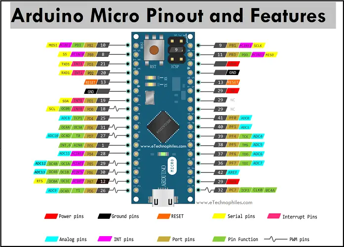
And the board features 20 digital inputoutput pins a 16 MHz crystal oscillator a micro-USB port an ICSP header pins and a RESET buttonArduino Micro pinout specifications schematic and datasheet is given below. It consists of a total of 20 digital IO pins of which 7 can be used as PWM outputs and 12 as analog inputs a power jack a micro USB port a 16 MHz crystal oscillator an ICSP header and a. Arduino Board Comparisons Picking The Right Board Pubnub.
You can place your ICSP header basically anywhere on your breadboard or perfboard or PCB simply connect the following lines to the pins you wrote down. Jan 07 2015 Arduino Leonardo Introduction. It has 20 digital input output pins 7 of which can be used as PWM output 12 of which can be used as analog input 16Mhz crystal micro usb socket power socket ICSP connector and reset button.
I have connected the ICSP headers to each other Ive tried it with just 3 jumpers - SCK MISO MOSI with 4 jumpers RESET with 5 jumpers Vcc. Arduino Uno is based on the ATmega328 by Atmel. The Arduino Micro is a miniature version of the Arduino Leonardo board.
Adrotate banner7 This is a 16 megahertz chip on in its. The Arduino Leonardo is a microcontroller board based on the ATmega32u4. That is the Arduino Uno V3 Pinout and the ATMega328P pinout as well.
It is even clarified by written those pins are for ICSP but what does ICSP mean and what are its benefits. The Arduino Leonardo is a microcontroller board based on the ATmega32u4 It has 20 digital inputoutput pins of which 7 can be used as PWM outputs and 12 as analog inputs a 16 MHz crystal oscillator a micro USB connection a power jack an ICSP header and a reset button. Arduino Uno is a microcontroller board based on the ATmega328P It has 14 digital inputoutput pins of which 6 can be used as PWM outputs 6 analog inputs a 16 MHz ceramic resonator CSTCE16M0V53-R0 a USB connection a power jack an ICSP header and a reset button English.
The Arduino Uno pinout consists of 14 digital pins 6 analog inputs a power jack USB connection and ICSP header. A slightly different chip to the uno is actually a very similar form factors of the you know but its actually a little bit different in quite a few ways in particular has a very different chip on board. The Atmega32u4 based Arduino Leonardo Pinout Pin diagram Schematic and Specifications are given in detail in this post.
They operate at 5 volts. Arduino leonardo pinout. This list is for 2x3 ICSP.
The Arduino Leonardo is a microcontroller board based on the ATmega32u4 It has 20 digital inputoutput pins of which 7 can be used as PWM outputs and 12 as analog inputs a 16 MHz crystal oscillator a micro USB connection a power jack an ICSP header and a reset. The Atmega32u4 comes with a built-in bootloader which makes it convenient to flash the Arduino board with our code. The Arduino Leonardo is a microcontroller board based on the ATmega32u4 It has 20 digital inputoutput pins of which 7 can be used as PWM outputs and 12 as analog inputs a 16 MHz crystal oscillator a micro USB connection a power jack an ICSP header and a reset button.
Each pin can provide or receive a maximum of 40 mA and has an internal pull-up resistor disconnected by default of 20-50 kOhms. In yellow the ICSP connector that connects to the ATmega328P. Please note that the Rev3 board has an ATMega 16U2 chip that manages the USB connection and also that chip can be reprogrammed via a dedicated connector labeled ICSP2 just.
In this post well go over the capabilities of the Arduino. The ICSP pin header is the six pins that are showed in this photo. In Arduino Leonardo pwm pinouts are 3 5 6 9 10.
The ICSP 6-pin header. The versatility of the pinout provides many different options such as driving motors LEDs reading sensors and more. First ICSP In-Circuit Serial Programming is a way that allows us to program the chips when they are in circuits in Arduino it.
It has 20 digital inputoutput pins of which 7 can be used as PWM outputs and 12 as analog inputs a 16 MHz crystal oscillator a micro USB connection a power jack an ICSP header and a reset button. More like this. It is an Atmega32u4 based microcontroller board.
If you are searching for Arduino Leonardo Icsp Header Pinout you've come to the ideal place. We have 14 graphics about arduino leonardo icsp header pinout adding pictures, photos, pictures, backgrounds, and more. In these web page, we additionally have number of graphics out there. Such as png, jpg, animated gifs, pic art, symbol, black and white, translucent, etc.


